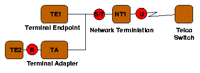

In Europe and Japan, the telco owns the NT-1 and provides the S/T interface to the customer. In North America, however, largely due to the U.S government's unwillingness to allow telephone companies to own customer premises equipment (such as the NT-1), the U interface is provided to the customer, who owns the NT-1. This effectively produces two incompatible varients of ISDN, which some manufacturers have attempted to remedy with devices (such as the Cisco 760) containing both S/T and U jacks.
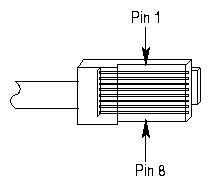
Normal ISDN devices plug into the S/T interface, an RJ-45 jack carrying two pairs of wires, each pair a current loop. As current flows into the positive line, it flows out of the negative line, maintaining a net balance between the two. The two lines should be grouped together on a single twisted pair, minimizing crosstalk between signals. One pair carries signal from the TE to the NT (user to network), the other pair carries signal from the NT to the TE (network to user).
| pin 3 | TE->NT + |
| pin 4 | NT->TE + |
| pin 5 | NT->TE - |
| pin 6 | TE->NT - |
The signals transmitted over the pairs are 192 kbps digital, using an Alternate Mark Inversion (AMI) scheme. Under AMI, one binary value (1) is indicated with no signal, while the other binary value (0) is indicated with either positive or negative signal, in alternating order. Thus, binary 00110101 would be signaled as +-00+0-0. The use of AMI ensures there will be no net DC signal, an important consideration since DC voltages won't be transferred by coupling transformers.
ISDN uses a 48 bit frame, transmitted 4000 times every second (once every 250 microseconds). Each frame includes several L (balancing) bits, which insert an extra positive signal if needed to DC balance the entire frame. A very similar (but not identical) frame format is used on the two pairs, with the TE to NT (user to network) signal synchronized with the NT to TE signal, delayed two bit times. The beginning of each frame is marked with an F (framing) bit, followed by a L (balancing) bit, both reversed polarity. This AMI violation provides a clear frame marker, but since two bits are both reversed, net DC balance is still maintained. In both directions, each frame contains two 8-bit B1 channel slots and two 8-bit B2 channel slots, for a net data rate of 8 bits/slot * 2 slots/frame * 4000 frames/second = 64 kbps on each B channel. Each frame also contains four bits of D channel data, for a net D channel data rate of 4 bits * 4000 frames/second = 16 kbps. In the NT->TE direction four E (echo) bits copy back the D bits from the other direction, providing collision detection for multiple devices competing for the D channel. An 8 kbps S channel (two bits per frame; not currently used) and an A (activation) bit complete the frame structure.
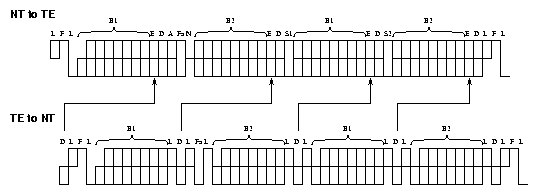
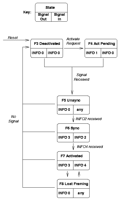
An ISDN TE goes through several states before becoming synchronized. The state diagram makes use of several signals, illustrated below. INFO 0 means no signal. INFO 1 is an unsynchronized signal sent from the TE to the network. INFO 2 is normal ISDN framing (NT to TE) with the B, D, E, and A bits all zero (others normal). INFO 3 is normal ISDN framing (TE to NT), carrying data and synchronized to INFO 2/4. INFO 4 is normal ISDN framing (NT to TE), carrying data with the A bit one. These signals can be observed easily with an oscilloscope; the only difficulty being synchronizing the scope to observe INFO 2, 3 and 4. A signal generator sending a 4 kHz square wave to the scope's trigger will due in a pinch.
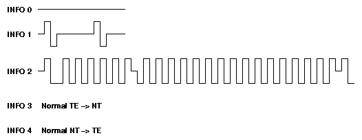
An ISDN circuit can be activated by either side of the link. TE requests activation by entering state F4 and transmitting INFO 1. NT requests activation by transmitting INFO 2, causing TE to enter state F5 (upon receiving signal) and then F6 (upon synchronizing with the framing bits). F7 is the normal data carrying state of an ISDN TE. These states have nothing to due with call setup or other operations over the B and D channels, though the TE physical layer must be in state F7 before any higher layer protocols can function.
