In my previous article, I gave an overview of the Guardian Alert radar system, disassembled one of the modules, and walked through a series of photographs as I described how the device operates. The most "interesting" part of the design, from an electrical engineering standpoint, is the microwave radar board. It contains an oscillator, the operation of which is described in U.S. Patent 6,064,276, a mixer, constructed from a diode pack, and a number of interconnections along with assorted fins, ground lines, and other bizarre shapes, all of which has some function at the 10.5 GHz operating frequency of the radar. This article focuses on the design of the fins used to isolate the microwave frequencies.
At low frequencies, and even into the radio frequencies, the lumped circuit model is widely used by electrical engineers to analyze analog circuitry. Circuit elements are represented by individual, discrete "lumps", mainly resistors, capacitors, inductors, and current or voltage sources, each behaving as an ideal component and interconnected by ideal wires. Complex devices such as transistors are modeled as a collection of ideal components. Even at UHF frequencies, the lumped model can still be used through careful placement of decoupling capacitors to isolate the power supply and bypass feedback paths, and the addition of additional circuit elements to model stray capacitances that would be swamped out at lower frequencies. SPICE and its varients is the most importance software tool for analyzing lumped circuit designs.
Around roughtly 1 GHz, though, the lumped circuit model becomes unusable. At 1 GHz, a wavelength in free space is 30 cm. In the typical PC board, with a dielectric constant of 2-5, the wavelength might only be 10 cm. Circuit elements on the order of centimeters now become a significant fraction of the wavelength. For example, on a circuit operating at 1 GHz, with a 10 cm effective wavelength in the PC board dielectric, moving 2.5 cm down a trace is equivalent to 90 degree phase shift in the signal. Corners, edges, and protruding fins produce more complex effects. Not only can these effects no longer be brushed away by careful board layout, but the clever microwave engineer learns to take advantage of them, implementing filters using the PC board's copper trace.
Towards the end of the twentieth century, the Finite-Difference Time-Domain (FDTD) method has emerged as most popular simulation technique for microwave circuitry. FDTD was originally proposed by Kane S. Yee in 1966, but only in recent years, as computers have become increasingly powerful, that it has emerged as the method of choice. FDTD is mathematically simple, based on a straightforward approximation of Maxwell's equations, and operates by "throwing CPU cycles" at the problem. It numerically solves Maxwell's equations for the entire simulated circuit, finding the electric and magnetic fields, as well as the charge distribution, to an arbitrary level of precision at each moment in a time series.
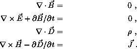
The FDTD approximation is based on the differential vector formulation of Maxwell's equations:

The E and D fields are both forms of the electrical field, differing from each other only in permeability of the material. In free space they are identical; likewise with the B and H fields. The divergence and curl required to compute these equations are approximated on a 3D Cartesian grid of Yee cells, in which the E/D and B/H fields are offset from each other by a half cell:
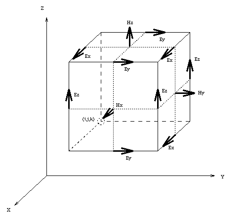
http://www.sethcorp.com/technical/fdtd.html
To illustrate the design process, I've analysed a copper shape that appears several times on the Guardian Alert microwave board. It's a copper fan, etched onto the circuit board as part of the copper trace, that acts a filter, isolating the 10 GHz signal. These fans appear on the power supply line to the oscillator (keeping high frequnecy noise out of the power supply) and on the output of the mixer, discarding the carrier components that would surely be part of the mixer's output.
I've modeled a similar, but not identical, fan in Cray's
lc program.
No, I don't have a Cray, but a Linux version is available.
Contact Kevin Thomas
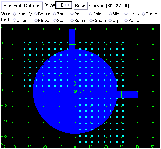
The fan below has about a 25 mm radius (the grid is in mm), and acts as a notch or rejection filter with a design frequency of 2 GHz. In the model, it floats 1 mm above a ground plane outlined with a red/white line. In reality, it would be seperated from the ground plane by the circuit board substrate, which would strongly affect the design because of it's non-unity dielectric constant. The area hashed in cyan is cut away from the model; only the solid blue areas are copper trace. Visible in the graphic is a voltage source (the red line at top) on the input lead, as well as probes (the green lines) on both the input and output leads. A probe exists on the input lead because I'm interested in reflections as well as transmissions, and the software uses boundary conditions to enforce a "no reflections" policy at the model's edge; outbound signals should just disappear.
The first thing I'm interested in doing is to analyze the response of the design to a Gaussian pulse, which contains elements of all frequencies, up to a practical limit set by the width of the pulse. By doing a Fourier transform on the signal, the entire frequency response of the circuit can be determined from its response to the Gaussian pulse. Here's an animation of the ground plane current during excitation by the pulse:

The animation clearly shows the incoming pulse, a portion that is passed through to the output, a portion that is reflected back to the input, and a portion that resonates in the fan, generating a complex "ringing" effect. The animation is nice to look at, but of more practical use is the voltage (and current) measurements made on the input and output traces during the simulation:
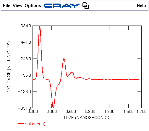
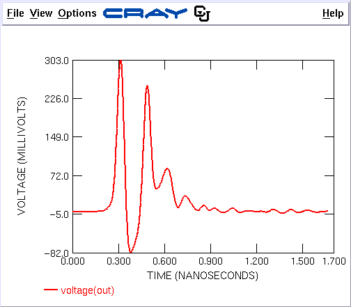
I manually split the input voltage into two parts. The first part (the initial .200 ns) is the incomming pulse, while the remainder is the reflection. The output, clearly showing the time lag of the circuit as well as its ringing response, doesn't need to be split. Now, the program does a Fourier transform on the three signals (input, reflection, and output) and plots the results by frequency:
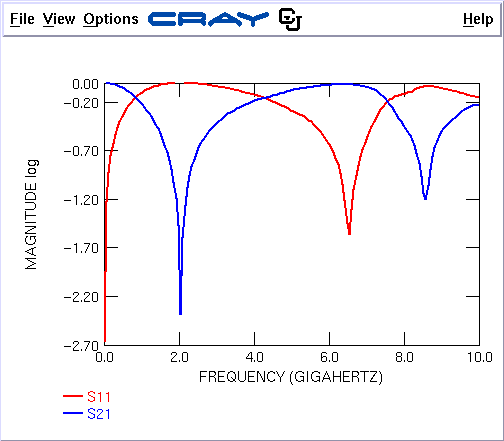
S11 is the port 1 (input) to port 1 response, in other words, the reflection. S21 is the port 1 to port 2 (output) response, in other words, the transmission. Clearly, there is a strong notch in S21 at 2 GHz, the frequency we are attempting to isolate. At this frequency, the fan's resonance should be just right to reflect almost all the input, and transmit nothing. Here is an animation of the circuit response to a 2 GHz signal:

Next is a final animation, this time of the circuit responding to a 4 GHz signal. Notice that at this frequency, the filter strongly passes the signal.

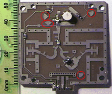
In the Guardian alert microwave board, the fan design is used in four places, circled in red below. The top two provide high-frequency isolation for the ground plane, the next one isolates the power supply, and the lower one passes only the low-frequency beat signal on from the mixer to the processor board. Intuitively, the fan passes D.C. and low-frequency signals, so its use in the circuit is as an RF choke, much as a choke coil might be used in a lower frequency design to supply power to an oscillator while at the same time isolating the high-frequency signal.
The alert reader will notice that I've only discussed the amplitude response of the circuit, while ignoring its phase characteristics. Some hint as to the phase response is provided by the visible time lag in the simulation output signal, which translates into a phase shift. Note that the reflected signal is inverted in polarity from the input signal, so the fan behaves as a short circuit, as opposed to an open circuit, which would reflect back without inversion. Due to the short wavelengths involved, the overall phase response depends heavily on the physical positioning of the circuit element. In this case, the fan would probably be positioned roughly a quarter wavelength from the signal trace it's attempting to isolate, thus insuring that its strong reflections interfere constructively (90° out; 90° back, and 180° due to the polarity inversion) with the signal it's isolating. In any event, a complete simulation of the entire circuit board would be done to validate the entire design.
ToyFDTD, a simple, well-commented, open-source FORTRAN program illustrating basic FDTD operation
lc, a fairly complete FDTD program used for the simulations in this article
U.S. Patent 6,064,276, describing the oscillator design
British patent 2,253,108, claiming the microwave motion detector
British patent 2,307,355, describing the mounting arrangement for the dielectric puck
Data sheet for Agilent ATF-36077, a transistor similar to the FHX35LPT used in the circuit
Data sheet for Siemens/Infineon BAT15-03W, the Schottky diode used as the frequency control in the oscillator
Data sheet for Siemens/Infineon BAT 15-099, the diode pack used in the mixer